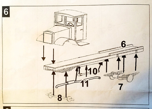
The irony is that the Zebrano YaG-6 kit isn't actually all that complicated - as you can see from the example of the assembly instructions that I have included above. And yet I feel mired in a succession of annoying little extra jobs just to get the kit to conform to the basic instructions.
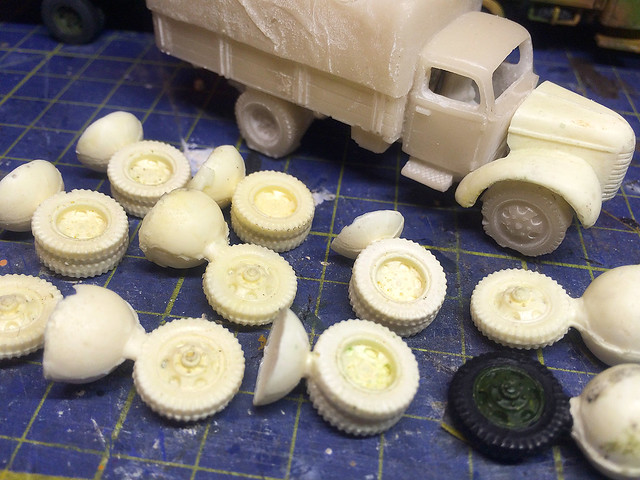
One of the minor irritations related to a short-run resin kit like this seems to be how the manufacturer chooses to cast his parts. Obviously this is a complex process and they are dealing with delicate components, so the kit makers tend to attache parts to sections of resin - the resin equivalent of plastic sprues - to protect them and to help in the casting process.
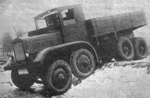 |
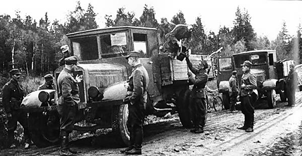
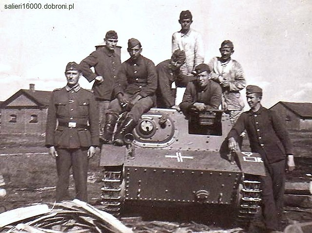
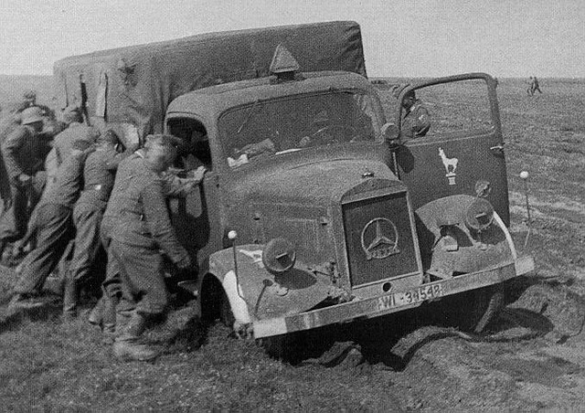
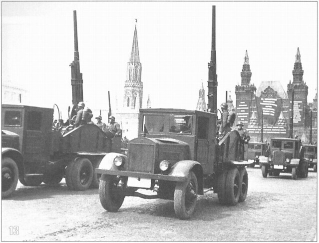
| Actually only tenuously related to this project, but interesting. This rather blurry photo shows a YaG-12. An experimental 1932 era 4-axle vehicle. The YaG's unique independent suspension was copied from an ingenious British design. |

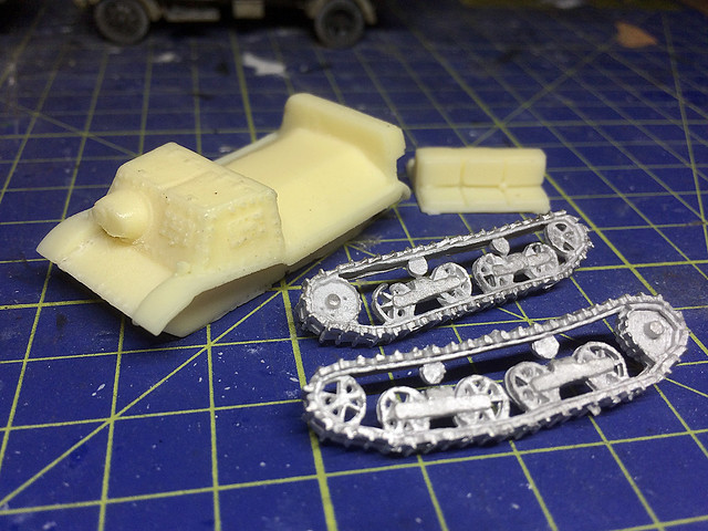
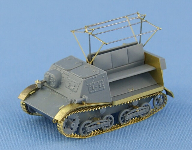
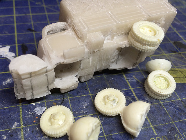
As you can see there is some nice detail on the chassis component - with the bottom of the engine block and front suspension moulded in between the front of the chassis frame.
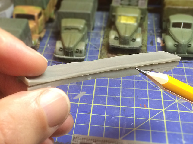
But as you can see in the accompanying photo the supporting resin slab is quite thick and fairly well attached to the frame, which means some careful but determined sawing or cutting to separate the two.
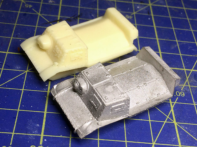
Having done that it's time to check all the various components that make up the chassis assembly...
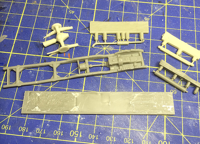 |
| Note the large slab of resin at the bottom of the photo - this was the supporting resin 'sprue' for the chassis frame! |
By means of deduction I managed to identify the front axel and the drive shaft. But Zebrano's drawing still leaves you scratching your head about the precise placement of parts. You can just about make out where the rear suspension is supposed to rest on the chassis frame, but the exhaust pipe will have you trawling the internet for any YaG-6 photos so you can work out where it goes.
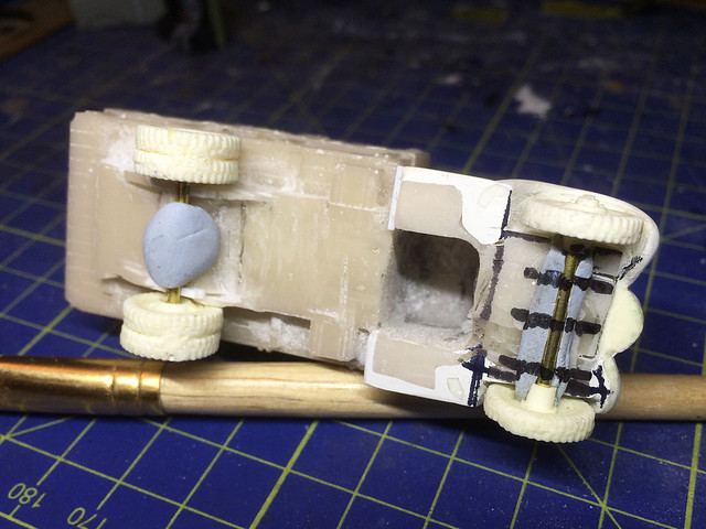
Unfortunately the best picture of the underside of a YaG-6 that I could find was a dodgy shot of the underneath of another YaG model...
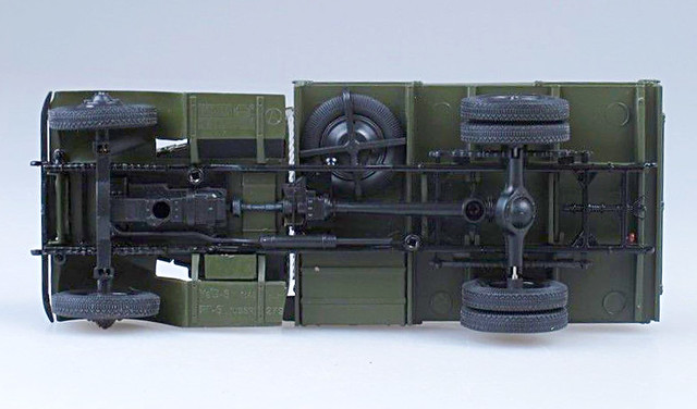
Still, this is quite useful as it shows that the exhaust pipe runs on the right side of the engine and down the inside of the chassis frame. It also shows the position of the spare wheel - which will be useful even though the Zebrano spare wheel is missing from my kit! [Also note where the front wheels lay in relation to those huge mud guards.]
 |
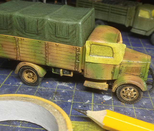
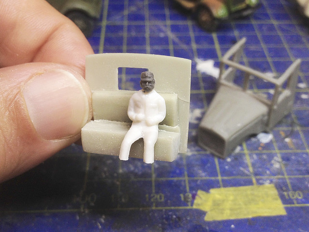
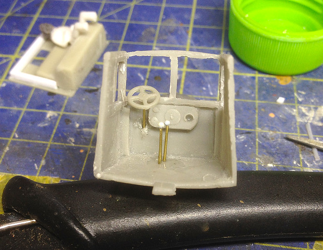
| In the end I had to build up the rear suspension and add better supporting posts to attach it to the chassis. I also extended the rear axel to widen the wheel base. I just put the exhaust where I felt it looked right. |

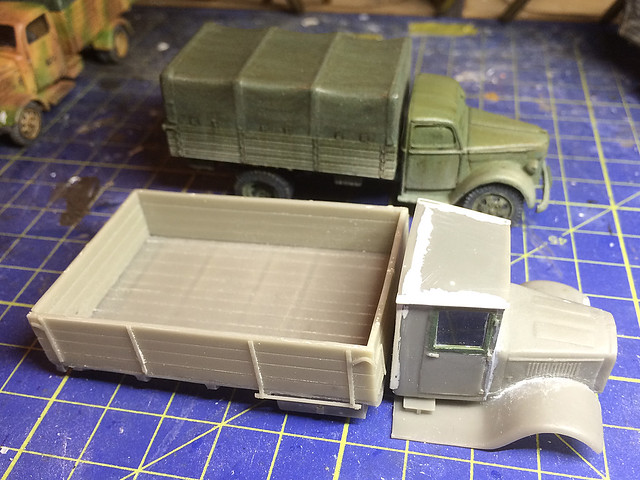
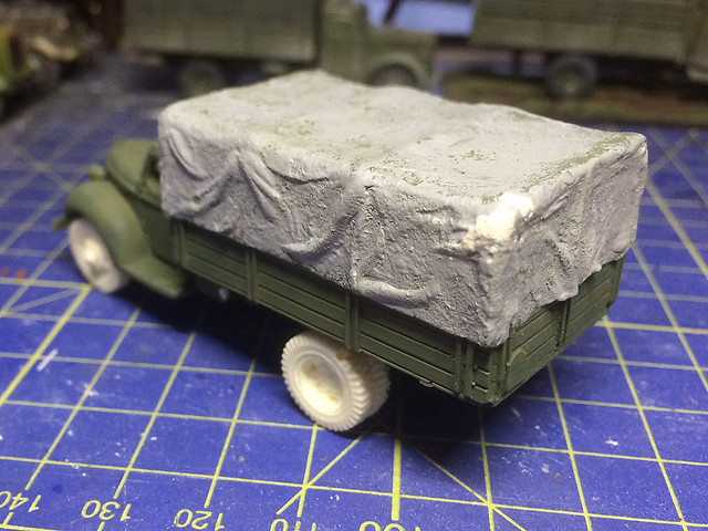
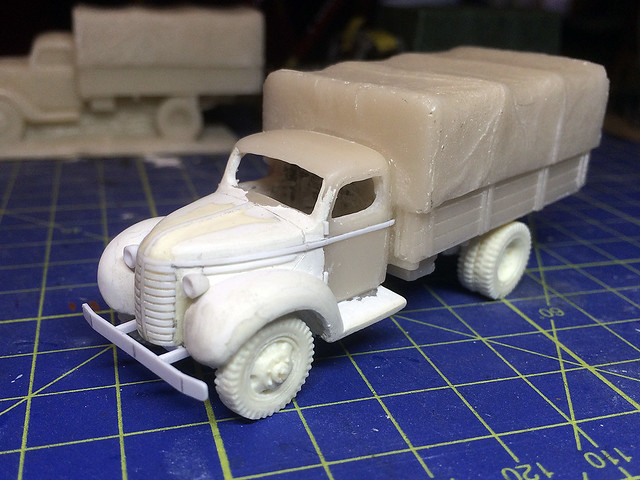
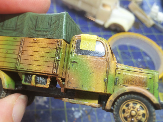
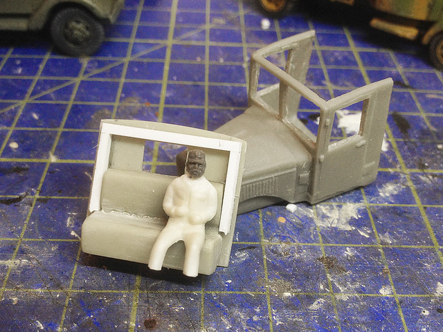
I couldn't resist dry-fitting the main parts together to get an idea of what the finished model would look like (and to check fit and dimensions). This did indeed highlight a problem - the rear wheels are supposed to come out to align with the edge of the flatbed, so I will have to make a longer axel.
 |
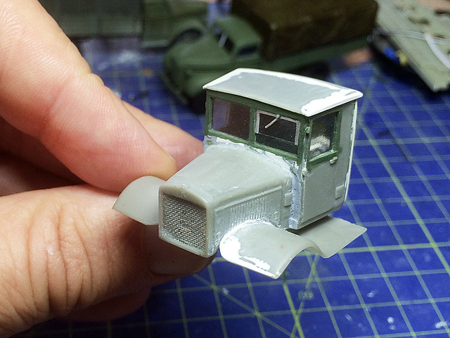
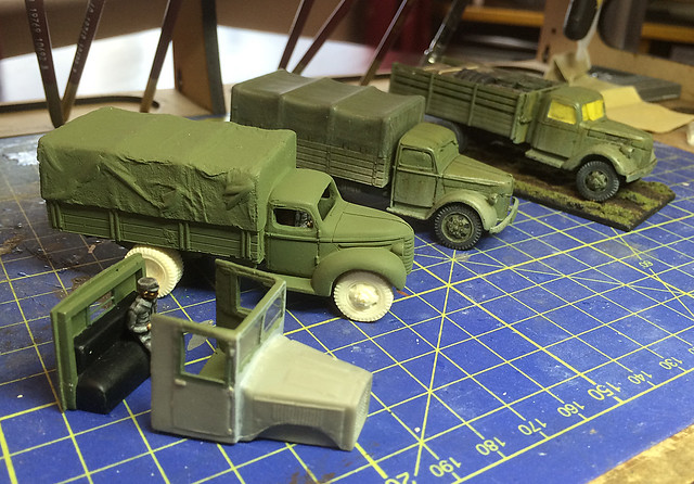
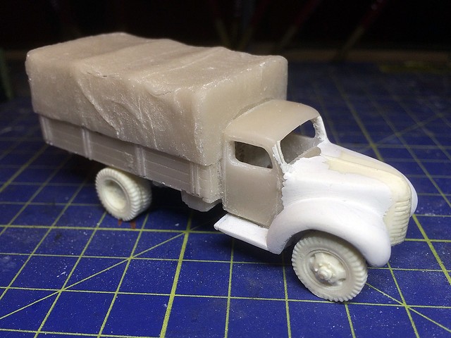
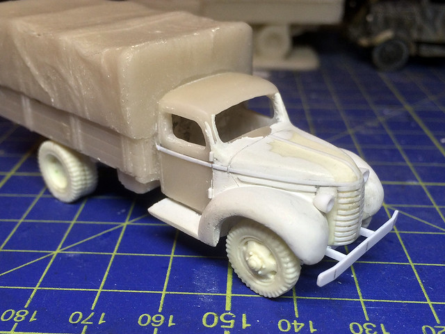
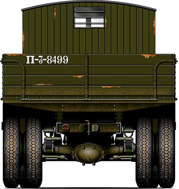
| Note the front fender over-hang. |
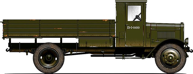
Left: Illustration reproduced with the kind permission of Oliver Missing of the 'Engines of the Red Army' web site. Source: © www.o5m6.de
Now, you might think that the same was true of the front axel and wheels, but actually these are in the right position and the huge fenders are supposed to over-hang to this degree. (But, yes, it does look strange.)
Well, it's getting there. There are a few things to sort out and some cleaning up and adding of little details. But the next post on this topic should be - fingers crossed - the base coating of the model.